Modeling and Control of an Electric Arc Furnace
Abstract— Model Based Predictive Control is a class of
computer algorithms that explicitly use a process model to predict
future plant outputs and compute an appropriate control action
through on-line optimization of a cost objective over a future
horizon, subject to various constraints. The cost function is
defined in terms of the tracking error (the difference between the
predicted output and set-point). Using this scheme, many different
MBPC algorithms have been proposed in the literature. This
paper presents an adaptive-predictive control algorithm, which
uses on-line simulation and rule-based control. The algorithm is
applied to an electrode position system of an electric arc furnace.
Electric arc furnaces are commonly used in steelmaking and in
smelting of nonferrous metals. To obtain the electric arc, usually
there are used three graphite electrodes . The power level depends
by the positions of the electrodes. As a result, the realization of a
competitive control system is very important because it led to
reduction of the energy consumption, pollution, and increases the
safety of the process.
I. INTRODUCTION
Model Based Predictive Control (MBPC) designates a very
ample range of control methods that make an explicit use of a
model of the process to obtain the control signal by minimizing
an objective function. The main ideas of MBPC are basically:
-explicit use of a model to predict the process output in the
future;
-on line optimization of a cost objective function over a
future horizon;
-receding strategy, so that at each instant, the horizon is
displaced towards the future, which involves the application of
the first control signal of the sequence calculated at each step.
Usually, the cost function is defined by using the output
prediction error relative to the system setpoint and the
weighted control signal, which can lead to a quadratic function
as follows:
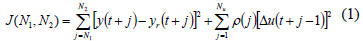
where y[.] is the predicted values of output signal, yr[.] is the
future setpoint, u[.] is the future control signal, N1 is the
minimum predicted horizon, N2 is the maximum predicted
horizon, Nu is the command horizon, ρ(j) is a control-weighting
sequence.
Performance of MBPC could become unacceptable due to a
very inaccurate model, thus requiring a more accurate model.
This task is an instance of closed-loop identification and
adaptive control. The difficulty of closed-loop identification is
that the input of process to be identified is not directly selected
by the designer but ultimately by the feedback controller.
The popularity of model-based predictive control is partially
explained by the fact that it uses traditional dynamic process
models which are usually available for design and/or
simulation purposes. At the same time, model-based predictive
control is being criticized by control engineers because of its
lack or weakness of theoretical background, having no
guarantee of convergence, stability, robustness, etc. in the
general case [1]. The extension of linear MBPC to nonlinear
processes is straightforward at least conceptually. But there
exists some difficulties [2]: the availability of nonlinear models
due to the lack of identification techniques for nonlinear
processes, the computational complexities, the lack of stability
and robustness results. A solution to increase the performances
is to use multiple models [3].
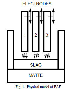
In the metallurgic industry for the melting of the scrap or
other metals it is used the electric arc furnace (EAF). The
electric arc allows to obtain high temperatures necessary to
melt or/and to realize some chemical reactions (fig. 1). To
obtain the electric arc, usually there are used three graphite
electrodes which are supplied by a three-phase power
transformer that has in the primer 20-30 KV respective 100-
800V in the secondary.
The electric power (10…100 MW) depends by the length of
the arc which can be controlled using an efficient hydraulic
control system of electrode position. The circuit closes through
the metal mass that will be molten. The principle needs a very
high-energy consumption, which implies a very efficient
control system to reduce as much as possible energy
consumption. Many times the weight of the electrodes is very
high; it could reach tenth of tons. The hydraulic control system
becomes complex. The acceleration and deceleration imposed
for the electrodes must ensure variable velocities from the
hydraulic control system with the aim of avoiding damage of
the resistance structure.
The electric arc appears when the electrodes are near the
metal mass. To close the circuit, the electric arc must to appear
at least between two electrodes and the metal mass. Usually the
distance between the electrode and the metal mass is 5-15 cm.
The resulted current is initially very high and is the duty of the
control system to move the electrode such that the current is
brought in normal limits. If the length of an electric arc gets
over a certain value, the electric arc extinguishes. In this case,
the positioning system must reposition in the correct form the
electrode so that the electric arc reappears. Another example is
the boiling phenomenon of the metal mass, which leads to a
variable length of the electric arc.
The realization of a competitive control system is very
important because it led to reduction of the energy
consumption, pollution, and increases the safety of the process.
For example, Siemens realized an application that uses
neuronal networks for the optimization of the control system of
the electrodes movement [4]. In addition, there are researches
regarding the use of the adaptive control [5], [6]. Modeling the
phenomenon that takes place in an electric furnace is very
difficult to realize [7]. Close to the hydraulic and electrical
subsystem, modeling can take into account the dynamic
models of the chemical and thermal processes [8] as well as
optimization problems [9].
II. THE MODEL OF THE ELECTRODE POSITION SYSTEM
To obtain an efficient control system, it is very important to
understand the mechanics of the hydraulic system that
positions the electrodes. A usual model is presented in [10]; in
this model, the electrode dynamics is modeled as a
combination of a mass, a spring and a damper, as in figure 2.
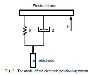
Thus, the dynamics of the electrodes are represented by a
damped second order system:
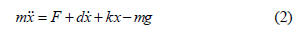
In this equation, x represents the electrode position, F is the
hydraulics force, d and k stand for the damper and spring
constants, m is the electrode mass and g is the acceleration of
gravity. Notice that the electrode mass changes, as electrode
materials are consumed during the steel-melting process. Due
to the considerable weight of the electrodes, moving them
upwards requires a much bigger force than in the opposite
direction. As a consequence, when designing an electrode
positioning controller, different gains should be used.
In [11] a simple second -order model of the electrode
positioning system is given by the following transfer function:
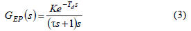
where K is the gain factor, τ is a time constant and the
exponential captures a delay of Td seconds. The parameters of
the electrode positioning transfer function were estimated
using measurements in closed loop.
III. A MODEL BASED PREDICTIVE CONTROL ALGORITHM
In [12] it was proposed an algorithm designed for
applications with constant setpoint (but arbitrary changed). The
main idea of the algorithm is to compute for every sample
period:
- the predictions of output over a finite horizon (N);
- the cost of the objective function (1),
for all (theoretically case) or a few (practically case) possible
control sequences:

and than to choose the first element of the optimal control
sequence.
For a first look, the advantages of the proposed algorithm
include the following:
-the minimum of objective function is global;
-it is not necessary to invert a matrix, therefore potential
difficulties are avoided;
-this algorithm can be applied to nonlinear processes if a
nonlinear model is available;
-the constraints (linear or nonlinear) can easily be
implemented.
The drawback of this scheme is a very long computational
time, because there are a lot of possible sequences. For
example, if u(t) is applied to the process using a “p” bits
digital - analog converter (DAC), the number of sequences is
2p*N . Therefore, the number of sequences must be reduced.
For a first stage, there were proposed the next four control
sequences:
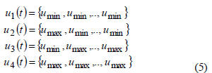
where umin and umax are the limits of the control signal.
Using these candidate control sequences it results four
output sequences y1(t), y2(t), y3(t), y4(t).
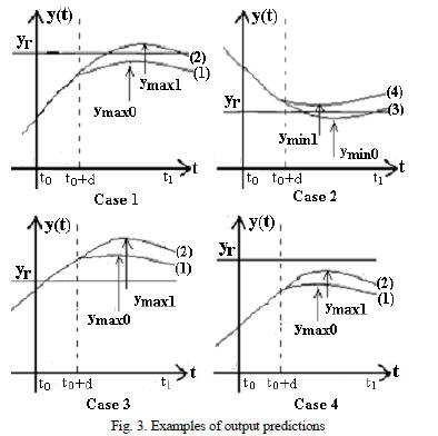
The control signal is computed using a set of rules based
on
the extreme values ymax0, ymax1, ymin0, ymin1
(fig. 3) of the output
predictions. It is considered four usual cases (yr is the setpoint,
d is dead time, t1=N):
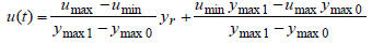
Case 1: If :
ymax0<yr (corresponding to u1(t) sequence)
ymax1>yr (corresponding to u2(t) sequence) (6)
Then:
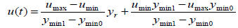
Case 2: If:
ymin0<yr (corresponding to u3(t)
sequence)
ymin1>yr (corresponding to u4(t) sequence)
Case 3: If:
ymax0>yr (corresponding to u1(t)
sequence)
Then u(t0)=umin
Case 4: If:
ymax1<yr (corresponding to u2(t)
sequence)
Then u(t0)=umax
In fig. 3, every output prediction curve is marked with a
number which corresponds to the number of control sequence
from relations (5). Analogous to case 3 and case 4, there are
two similarly cases if dy/dt<0 for t<t0.
In the second stage, depended by the behaviour of the
control system, it is used an algorithm that modifies the limits
of control signal:
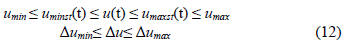
In relations (5)…(11), the values of umax, umin
are replaced
with uminst(t), uminst(t).
IV. THE CONTROL OF THE SYSTEM
The previous sections indicates the fact that the modeling
of
the process in an electrical arc furnace it is difficult to be
realized and exists more aspects that cannot be sufficient
known.
During furnace operation, the characteristics of the bath
change as the solid scrap melts into liquid steel, until metal
pool. This leads to large changes in the charge conductance; it
is possible to consider this variation as a disturbance to the
process. The main disturbances to the process are due to scrap
movements, mainly in the beginning of the melt-down, when it
not exists a liquid bath. As a result, some times the scrap
touches the electrodes, which cause short circuits. Another
problem is the strong coupling effect between the electrodes.
This means that when the position of one electrode is changed,
the currents in the others also changes.
As a consequence of the parameter variations of the
process
as well as the fact that the process’s model can present many
unknowns, it is justified the usage of the adaptive control. In
what it follows, it will be made the assumption that each
associated subsystem to the three electrodes may be
approximate by a linear parametric model with unknown
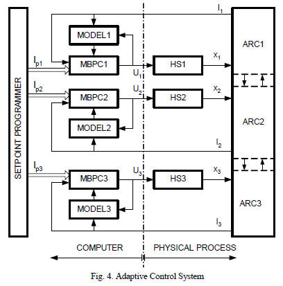
parameters that follows to be on-line identified. In figure 4 it is
presented the bloc scheme of the proposed control system.
Used notations:
-MBPCk, k=1..3 - model based predictive control
algorithm;
-Modelk, k=1..3 - subprocess model of electrode positioning;
-HPk, k=1..3- k hydraulic subsystems;
-x1..x3 – positions of the three electrodes;
-I1p..I3p – setpoint values of the currents on the three
branches;
-I1..I3 – electrical currents on the three branches;
-u1..u3 – command signals of the hydraulic actuators;
It is used a linear model of the form:

where y[.] is the output signal (electrical current), u[.]
is the
control signal (command signal of the hydraulic actuators), n,
m define the model dimension, d is dead time, ai, bi are
process’s model parameters.
In the practical implementation, the control algorithm
will
receive as input data the measured currents on each electrode
(these currents depend obviously also on the length of the
electric arcs) but also information concerning the electrical
voltages measured on arcs. The adaptive control algorithm will
assure control signals u1, u2, u3 necessary for
desired
positioning of the electrodes in such a way that by each branch
to be realized the prescribed electrical current. The signal pairs
(uk, ik – k=1..3) are used by the Modelk,
k=1..3 blocks to
realize the experimental identification of the parameters of the
three models. Identification may be realized by example by
using the recursive least square algorithm.
Certainly, on the experimental basis it must be
established a
sampling period, the dead time and the parameters that define
the dimensions of the model process (n, m).
To be able to test (by simulation) the proposed system,
the
process has to be simulated (including the hydraulic part). For
the electrical part it will be adopted a model in direct current
that although it is very simple, it leads to obtaining of some
nonlinear calculus relations. It is considered that, in conditions
that the arc is active, and then its resistance is proportional with
its length:

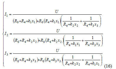
In figure 5 it is presented the simplified scheme of the
electrical parts. It can be written the following relations:
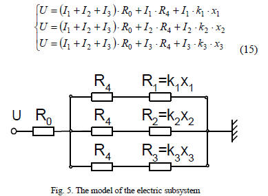
Solving this system it is obtained:
Taking into account the equations (2) and (3), for
modeling
the hydraulic subsystem that can be used the equation forms
(13) in which can be choose the structure parameters (m, n, d)
as well as the model parameters ai, bi.
Let’s make some remarks:
- usually it may be considered k1=k2=k3; it was
used the
different coefficients to study what’s going when the forming
conditions of the electrical arcs on the three electrodes differs
due some known or unknown reasons ;
- in a real implementation, the output of the hydraulic
system
respectively the distances between the heads of the electrodes
and melting are not known. The output signals from the
process are currents and voltages of these can be measured.
- for simplification of the application, there will be
considered as the output signal from the process that will be
controlled, the electrical currents through the three electrodes.
It has to be mentioned although, that usually are controlled the
impedances on each channel or the consumed on each canal [7], [13];
- due to the way in which it is formed or are extinguished the electrical arcs, the control algorithms must use a set of rules that it implements the different conditions. Let us consider the initial phase in which all the electrodes are far from the metal mass. It may be taken into account different strategies of approaching the electrodes of the metal mass. In the moment in which one of the electrodes reach the metal mass, this thing may be seen (I≈0; Uarc≈0) and the motion of the electrode must be stopped. When the second electrode reaches the metal mass, there are created the conditions for activation of the electrical arcs that leads to the appearance of the very large electrical currents. The control system will have to position the two electrodes thus the electrical currents to have the desired value. Activation of the third electrical arc will be made if the distance from the electrode and metal mass is sufficient small. In a similarly way it has to be adopted strategies for situations that can appear: extinguished the electric arcs, reaching the electrodes to the metal mass etc.
- due to the particularities of the process, the identification operation of the process parameters will be deployed only when there are fulfilled some certain conditions (e.g. all the electrical arcs must be activated).
The model process may be used for on line simulation of the system’s behavior for a number of control sequences.
By analysis and interpretation of the resulted output sequences, it is possible to compute the control signal considered optimal at the respective moment. Such an algorithm that uses on-line simulation and rule-based control is presented in [14], [15], [16]. The algorithm has the advantage that permits the direct use of the nonlinear model of the process and permits easy implementation of some conditions presented previously.
V. SIMULATION EXAMPLE
Based on what was previously shown, it was realized an application [17] that permits simulation and testing the identification algorithms and control. Application permits:
- choosing the type of the algorithm (On-Off, PID, adaptive-predictive) used for controlling the position of each electrode and choosing some parameters of the control algorithms;
- choosing the process parameters: order (np, mp, dp) of the hydraulic system, the characteristics of the electric system (r0, r4, k1, k2, k3 from fig. 5), volumetric efficiency of EAF;
- choosing the order of the process model as well as of some parameters of the identification algorithms (forgetting factor etc.);
-introduction of some perturbations: interrupt arc, scrap break down, random length of the arc, noise on current measure, changes on scrap surface.
The user can modify during the simulation most of the control algorithm parameters and of identification, the process characteristics; it can be chosen different algorithms of control for the three electrodes.
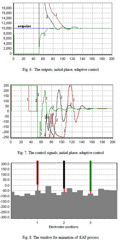
In fig. 6…8 is presented an example of evolution of the outputs (electrical current) of the control signal as well as the window for animation of the EAF process. It was used model based adaptive control. There are used different coefficients (k1=0.0003, k2=0.0005, k3=0.0007). It was noted 1, 2, 3 the corresponding electrodes signals 1, 2, 3.
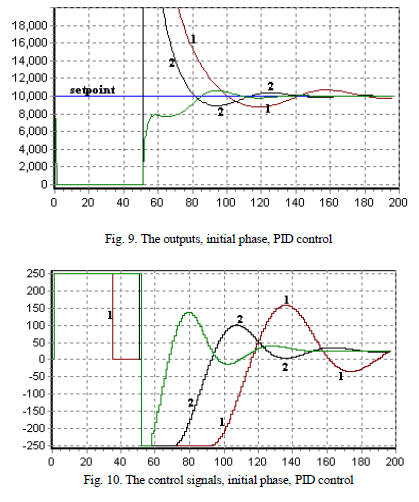
In fig. 9, 10 are presented the behavior system in the case of PID controller’s usage.
VI. CONCLUSIONS
In this paper were presented some aspects concerning the modeling and adaptive control of the position of the electrodes in an electrical arc furnace. The realized application [17] permits testing the control algorithms, study of the error effects on modeling, simulation of perturbations etc. For facilitating the practical implementation, application can be developed by extend of the possibility of choosing the component subsystems, using the multiple models, optimization strategies, etc. Application was realized by using Delphi environment, also used in other control applications for EAF [18]. Taking into account the complexity of the problems, an approach that will be used in the future includes usage of the Matlab-Simulink modeling and simulation environment [19] as well as dSpace equipments [20] for testing the ECU.
ACKNOWLEDGMENT
This work was supported by the Ministry of Education and Research grant CEEX 112 INFOSOC program. Grant’s title: Simulation, Control and Testing Platform with applications in Mechatronics.
| Prev | Next |