Thank you for visiting our site! You landed on this page because you entered a search term similar to this: solve nonlinear differential equation first order.We have an extensive database of resources on solve nonlinear differential equation first order. Below is one of them. If you need further help, please take a look at our software "Algebrator", a software program that can solve any algebra problem you enter!
GettingStarted Doing Simulations
WhySimulate?WhatIs A Simulation?
WhySimulate?
Anotherlesson has discussed why you need to do simulations, and for the needto have a model of your system that is in a form you can use for computation. Of course, your level of trust in your prediction will depend upon howwell you modelled your system. That's another story. We'llstart by discussing how to get started doing a simulation. First,the goals for the lesson.
Given a first order system,
Be able to simulate the system using the Euler integration algorithm.
Be able to choose a good time interval for calculation using that algorithm.
WhatIs A Simulation?
A simulation is a mathematical calculation of a system's response. The results can be presented in a number of ways, including numerical results,graphical plots, etc. The intent is to inform the designer aboutwhat is going to happen.
What Do I Need To StartSimulating?
Well, the first thing you need is a good mathematical description of yoursystem. You need a description that you can use to make predictionsof how the system will behave as time goes on when it is operating. In other words, you need a dynamic description like a transfer function,a differential equation or a set of state equations.
What Kind Of DescriptionWorks Best?
You don't have much choice here. If you want a good general way todescribe a system you pretty much have to use a set of state equations.
- You might think that transferfunctions would be the most useful!
- But what often happensis that a designer uses the best linear model available - in the form ofa transfer function - to design the system, but, in the back of the designer'smind is the recognition that every system has nonlinearities.
- But, there are not manyanalytical tools available for general analysis of nonlinear systems. Most of the analytical tools available - Laplace transforms, frequencyanalysis, etc. are for linear systems only.
There's an old adage - "If the only tool you ownis a hammer, then after a while everything looks like a nail." Analytical tools for system design focus on linear systems.
Howcan you predict how a system will behave when you account for the nonlinearitiesin the system?Ifyou have a system that is nonlinear, you linearize it and use your linearanalytical tools.
Whenyou're done with your design, you then try to account for nonlinearities.
So,the question comes down to this. How can you predict how a systemwill behave when you account for the nonlinearities in the system?"
The process is straight forward.Thereare standard numerical techniquesfor solving nonlinear differential equations.
Thatprocess of using numerical techniques to determine numerical solutionsis called simulatingthe system or simulation.
Stateequations are the commonest way of describingnonlinear systems and produce a model form that can be used in most simulationsoftware.
Remember,you may dread working with state equations, but if you've ridden an airplanerecently you put your life in the hands of people who used state equationsto predict the aircraft's behavior - and it's always nonlinear - so youhave to deal with them.Determinea set of state equations for your system, including any nonlinear effectspresent in your system.
Codethe resulting set of nonlinear differential equations for use in a standardset of simulation software. You can use Mathcad, Matlab, or Simulink,for example.
Computethe system's response. Do that for a variety of conditions that arerepresentative of actual operating conditions - including extremes.
In order to understand simulations, we need to start with a simple example.
- Theexample will be a first order system with a transfer function:
- Here:
- G(s) = the transfer functionof the system
- X(s) = the output of thesystem
- U(s) = the input of thesystem
- Gdc= DC Gain of the system
- t= Time Constant of the system
G(s) = X(s)/U(s)= Gdc/(ts+ 1)
- This system satisfiesa differential equation given by:
dx(t)/dt = - x(t)/t+ Gdcu(t)/t
- This differential equationis written in a form that emphasizes that it is really a state equation- the only state equation - for a first order system. That form isthe second equation above where the derivative of the output - the state- appears on the left hand side of the equation and everything else ismoved to the right hand side of the equation.
Youshould realize that a choice means a difference. They don't all givethe same numerical results. Some are more accurate than others.
We'regoing to start by looking at the simplest algorithm possible.
TheEuler Integration Algorithm
To understandthis algorithm, consider the situation below. Assume that
we have done the computation to sometime, t.
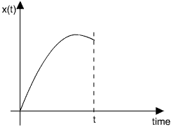
Now, if we have the computation to some time,t, call the value we have x(t).
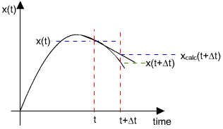
Fromthe diagram above, we can get an approximate value for x(t + Dt).Ourgoal is to compute the next point, x(t + Dt).
Thesimplest way to estimate x(t + Dt)is to extrapolate the slope, as shown in the figure below. That figurealso shows the danger of that simple extrapolation. A linear extrapolationwill not follow the curve of the true function, x(t).
Wecan develop an expression for x(t+Dt)in terms of the value know at an arbitrary time, t.
x(t + Dt)~= x(t) + Dt* (dx/dt)|t.
Now,here's the algorithm. Actually, it's called the Eulerintegration algorithm.Thissimply extrapolates the slope from a starting value of x(t).
Theslope at time t, is denoted by (dx/dt)|t.
Now, let us look at how the Euler integration algorithm works for the simplefirst order linear system we mentioned earlier. We will do this calculationassuming that the system has a constant input. Here's the transferfunction of the system we will be working with.Youneed a starting value for x(t). Normally, that is the value at somearbitrary time assumed to be t = 0.
Computex(t + Dt) ~= x(t) + Dt * (dx/dt)|t.
Repeatthe second step above until the computation covers the time needed.
A side note: The Euler integration algorithm is one algorithm used when integral controlis implemented digitally. Site of a future link to that lesson.
G(s) = X(s)/U(s) =Gdc/(ts+ 1)
Now, there are numerous different waysthat you can implement this algorithm, including the following.Let'sbe clear about the situation.
- We will assume that x(0)= 0. In other words, the system starts from rest.
- We will assume that theinput, u(t), is a constant.
- We will use the simplestnumerical example possible, then try to generalize later to different situations.
Next,we compute x(t + Dt)~= x(t) + Dt* (dx/dt)|t, and the value we use for the derivative is:
dx(t)/dt = - x(t)/t+ Gdcu(t)/t
- In Mathcad using the programmingstructure. tosee that.
- In C using functions forthe Euler algorithm and the state equations. to see that.
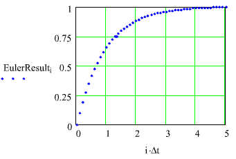
This simulation is done for a first order,linear system with a transfer function, G(s) = Gdc/(ts+ 1).
Whilethe simulation results look like what we might expect, it is not clearhow exact these results actually are. The next plot shows the calculatedresults - in blue - along with the theoretical solution - in red. Actually, by choosing a linear, first order system, where we know the theoreticalresults, allows us to see how well the algorithm performs.Thesystem has a DC gain, Gdc = 1, and a time constant, t= 1.
Forthis simulation, Dt= 0.1sec, which is one-tenth of the time constant, t.
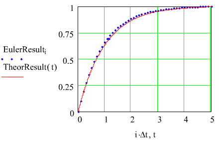
While the solution looks reasonably good, close inspection shows that thecalculated results seem always to lie above the theoretical result. It is interesting to see how things change as the time interval for thecalculations, Dt, is changed. Here are the results when Dtis increased from 0.1 sec to 0.2 sec.
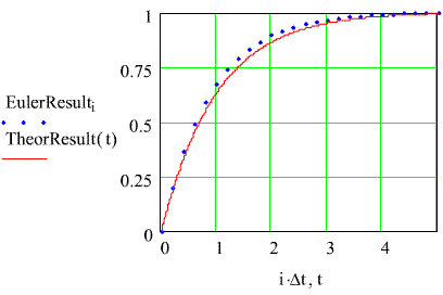
It's reasonable to expect accuracy to deteriorate as the calculation intervalis increased. If we revisit the expression for the Euler algorithmcalculation it is really just a short Taylor Series expression.
x(t + Dt)~= x(t) + Dt* (dx/dt)|t
From what we know of Taylor Series we knowthat the approximation is better when the calculation interval is smaller.
Anyhow, take this a little further and increase the calculation intervalto 0.5sec. Here is the result.
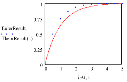
You can see that, as the calculation interval is changed, that the generalshape of the computed solution looks like the theoretical solution butthat it just lies above the true solution. It would be dangerousto generalize that from what we have. If we change the calculationinterval even more some strange things begin to happen. Here is theresult when Dt= 1.0. We've increased to size of the dots for the calculated responseto emphasize what happens for this calculation interval.
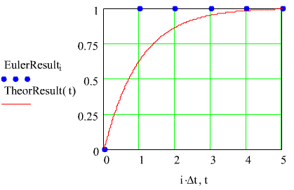
One needs to ask "What is going on here?". Note the following about this calculation
Nowexamine a calculation interval for Dt= 1.2 sec. That pushes the calculation interval just beyond the valuethat produces the instant jump to steady state. Here's the result.Uponfurther reflection, the first point calculated - at one second - is exactlyone - the steady state value.
Oncethe steady state value is reached in the computation, the calculated derivativeis zero, so the calculation doesn't change after that.
Wecan probably conclude that we should always use a small Dtwhen we do a simulation. The general rule is to use a Dtthat is an order of magnitude smaller than the time constant, t. We've done this calculation with a time constant of one second. It'sthe ratio of the calculation interval to the time constant that is important.
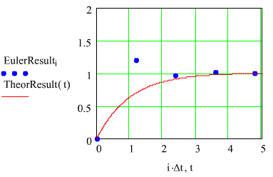
There'sa new phenomonon in this calculation - calculationovershoot and oscillation. You probablynever saw that before. The lesson here is that the calculatedresponse doesn't even have to have the same form as the theoretical response.
It'sgetting worse all the time.....
Theworst is yet to come. Let's try an evenlarger time interval, Dt= 2.0 sec - twice the time constant .
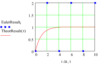
Thisis another new phenomenon- sustained oscillationsin the calculations. Have you seen that before? Youhad better think about that. The calculated solution doesn't looklike the theoretical solution, it doesn't converge like it should. You should be getting to the point where you stop believing in calculationsjust because they are done by computer. Remember this fundamentallaw.Now,the oscillations persist. Note we had to change the scale to showyou the top points in the oscillations.
Thesolution doesn't converge to the steady-state value. It just oscilatesaround the steady state value.
Itgets worse for larger intervals.
Any calculationimplements an algorithm, and the solution is only as good as the algorithm,even if the calculations are carried out to 359 decimal places.Now,let's crank it up another small notch. Do a calculation forDt= 2.5 sec. Here's what you will get. Notice that we changedthe scale another time, and we still get this one dot way out here! It's actually part of the plot and we decided to include it FYI.If you believe anycalculations just because they are calculations, then you better rememberE. J.'s variation on Barnum's Law - Barnumunderestimated the birthrate.
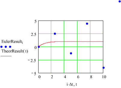
It gets worse for larger intervals. If the interval is larger, thecomputed solution grows even faster, but you should get the point by now.
SummingIt Up
The simulation of the first order system that we have been examining showsus several things that can happen when you use a simulation algorithm tocompute a system response.
Ifyou choose your computation interval to be small enough, then you can getan accurate calculation of the system response.
What ElseIs There To Be Concerned About?Theupdate algorithm depends upon the ratio Dt/t. Accuracy and stabilityin the calculation depend upon that ratio.
Toolarge a calculation interval can lead to disastrous failure.
The example we have been using has highlighted features of simulation calculations,but there are other things to be concerned about.
Wehave only looked at a first order system. We need to examine howto simulate higher order systems. We'll find that we need to worryabout how to get a state description of a system.
Oursingle example was a linear system. We need to look at how to simulatenonlinear systems. to go directly to that lesson. LINK TO BE IMPLEMENTED LATER.
Weonly looked at one integration algorithm, the Euler integration algorithm. However, while there are more complex/more accurate algorithms, most ofthem share the characteristics we found in the Euler integration algorithm.
