Thank you for visiting our site! You landed on this page because you entered a search term similar to this: Like Terms Simplifying Algebraic Expressions Junior High.We have an extensive database of resources on Like Terms Simplifying Algebraic Expressions Junior High. Below is one of them. If you need further help, please take a look at our software "Algebrator", a software program that can solve any algebra problem you enter!
Binary Numbers, Boolean Algebra and Digital Design
Including switches and relays
Binary Numbers
The representation of numbers by the binary digits 0 and 1 in positional notation is an "easy piece," and won't be explained in any detail here, since the reader will probably already know a good deal about it. Binary numbers should be introduced in grade school, since they are easy and give insight into the usual decimal number system.
Consider the number 1011011000111000 = 46,648. Each 1 or 0 is called a bit, short for binary digit. The binary to decimal conversion can be carried out (tediously) by adding the powers of 2 corresponding to the 1's in the number. Copying the number means referring back and forth between original and copy, since one cannot remember all the 1's and 0's in proper order unless one is an idiot savant. Such operations are facilitated by coding the binary number, which is grouping the digits and giving symbols to the groups. Hexadecimal coding is the favorite method, in which the bits are grouped in fours, and the numbers 0-9, A-F are assigned to the groups corresponding to their values. The only disadvantage of hexadecimal is the necessity for introducing the symbols A-F for 10-15. If we group by threes instead, we need only the digits 0-7. This octal coding was once frequently seen, but has now fallen into desuetude.
Our binary number is B638 in hex, sometimes expressed as $B638 or B638H to show it is hexadecimal. That's obvious here, because of the B, but 638 (decimal) is certainly different from 638H = 1592. In C, we would write 0x638. To convert to decimal, you take the first digit and multiply by 16, then add the second and multiply by 16 again, and so on, until reaching the final digit, which is simply added. A similar rule, but with division by 16, converts from decimal to hexadecimal. There are also ways to express decimal fractions as hexadecimal fractions and vice-versa, but this is seldom required. So, normally we handle binary numbers as hexadecimal for the usual operations of arithmetic.
Negative numbers are represented by 2's complement, which is what you have to add to them to get all 0 bits, with the highest bit pushed up outside the range of the numbers being considered. Suppose we consider 8-bit numbers (bytes). 01111010 = $7A = 122 is represented in 2's complement by 10000101 + 1 = 10000110 = $86 = 134. If we add 122 + 134 we get 256 = 100000000, which in 8 bits is just 00000000 = 0. Therefore, if we add the 2's complement of a number to another, it is the same as subtracting the first number from the second, if we drop the ninth bit. If we use the 2's complement convention for negative numbers, note that the 8th bit is 1 for a negative number, 0 for a positive one. Therefore, we can represent signed numbers from -128 (10000000) to +127 (01111111) with only one representation of zero, 00000000, with 8 bits. Computers handle negative numbers this way, since only the usual binary arithmetic is required.
Boolean Algebra
In general, algebra represents quantities as symbols which are manipulated according to certain rules. Geometry represented such quantities as the lengths of lines, which were manipulated by the processes of geometry, which is usually a much more difficult matter. Algebra, a word taken from Arabic, is the only major contribution of the Arabs to mathematics, though they appreciated and studied the subject with great intelligence. It was developed in its present form in Italy in the 15th and later centuries, where many new problems were solved, and became an essential part of the new infinitesimal analysis known as the Calculus, and through this the basis of mathematical physics.
There is a more restricted definition of an algebra in mathematics: "An algebra A over a field F is a system consisting of a set S of two or more elements a, b, c, ... and three operations +, × and · such that + and × may be performed on any two elements of S producing a third element of S called the sum or product of the two elements, and · on any element α of F and any element a of S to produce the scalar product of α and a. + is commutative and associative, · is commutative and associative, and distributive over addition, and × is distributive with respect to addition, and associative for what are termed associative algebras (Dickson)." Ordinary or complex numbers are fields.
George Boole (1815-1864) introduced what has become known as Boolean Algebra as a mathematical representation of propositional logic, where statements could be either true or false, and nothing else. Symbols representing these values could be manipulated according to certain rules to demonstrate the consistency of a chain of reasoning, or to find new results proceeding from the old. We have symbols and two operations on them, but no scalar product (and so no field F), plus some additional operations peculiar to quantities that take two values only. Therefore, Boolean algebra is not strictly an algebra, but only one in a general sense.
Boolean algebra applies wherever we have quantities that can assume only one of two values, and so has a remarkably wide field of application and a very practical one. It can be applied abstractly to sets of objects, where the binary thing is inclusion or non-inclusion (algebra of classes). The calculus of propositions applies to statements that are either true or false, with a variety of connectives, not simply the two of an algebra, but expressible in terms of them. A switch is either open or closed, another binary variable, so switching algebra is an application of concern to us here. Digital signals, which assume only two values, are another application closely related to switching algebra. Boolean algebra is fascinating to study, which is perhaps the principal reason for considering it, but it can also give some help in the specification and design of switching or digital networks. This help is valuable, but often over-rated. Boolean algebra by itself cannot solve practical problems.
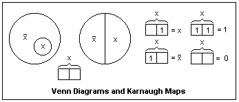 In the diagram at the right, let the large circles enclose all the points under consideration, a universe or population represented by I or 1. If the answer to "is every point included" is yes, then this is represented by I. The small circle in the left-hand diagram represents those points in a smaller set, denoted by x. The Boolean variable x is 1 when a point is in the smaller set, 0 when it is not. That is, x is a function over the points of the complete set I, that is 1 for points inside the small circle. The Boolean variable /x (x bar is represented in this way in text because of limitations of the display) could be represented by any other letter, say y, but /x shows that it is a Boolean variable that is 1 for all points not in the set x, called the complement of x. Exactly the same things are represented by the circle at the right divided into right and left halves. The only difference is the precise set of points represented by x, which is of no importance in the algebra. Therefore, the regions in such diagrams as these, when expressing general algebraic relations, are of arbitrary shape and size. These are called Venn diagrams, and are useful for visualizing Boolean algebra.
A special form of the Venn diagram is the Karnaugh (K-) map. For one variable x, these are the 2-cell figures shown at the right. Each cell represents an elementary area in the Venn diagram. The cells may also be labelled by the values of the variable, 0 or 1, instead of by the convention shown, and this is usually done in digital design. Each cell may contain a 1 or be left empty, which is equivalent to a 0. The functions x, /x, 1 and 0 can be represented as shown. At this point, the K-maps are only curiosities.
For example, by inspection of the diagrams, we find the algebraic rules that x + /x = 1, and //x = x. Here, the symbol + represents the union, meet or join of the two sets, often represented by the cup operation, the symbol for which is not supported by browsers. Inversion is the operation of taking the complement of x, or /x, and we see that inverting the inversion gives the original variable back. In logic or circuits, the similar operation is called OR. Imagine switches representing x and /x (one closed when the other is open) in parallel.
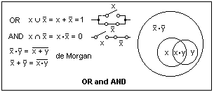 This is shown in the diagram at the left, which shows alternative ways of representing the basic operations of OR and AND, by cup and cap, by + and · or by switches in parallel and series. A Venn diagram that shows two subsets x and y illustrates what happens for different subsets. The region /x·/y is the area outside both circles x and y, that is outside x + y, while x·y is the area within both, outside /x + /y. These areas are mutually exclusive, and so are the complements of each other, which gives us de Morgan's theorems, a very important result in Boolean algebra. Note that x and y refer to the complete circles, not just to the area the letters are in. What are these areas? (x·/y and y·/x). We can split the Venn diagram into elementary areas, and combine these in various ways, which is equivalent to doing algebra with the symbols, applying the rules of Boolean algebra.
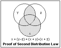 It is clear that OR and AND are associative and commutative, like ordinary addition and multiplication. However, not only is x·(y + z) = x·y + x·z as in ordinary algebra, but also x + (y·z) = (x + y)·(x + z). Indeed, x·x = x and x + x = x, so that any element is idempotent. These rules can be proved with Venn diagrams. The proof of the second distributive law is shown at the right. The dotted area can be expressed in two ways, which gives the result. It is mainly the idempotency and the second distributive law that make Boolean algebra seem strange, but it is all quite valid. Indeed, we have 1 + 1 = 0 + 1 = 1 + 0 = 1, and 0 + 0 = 0. Similarly, 1·1 = 1, 1·0 = 0·1 = 0·0 = 0. Strange but true.
Useful relations are z + (y·z) = z and z·(y + z) = z, called rules of absorption or covering since y disappears. Both are fairly obvious by inspection (y·z cannot be 1 unless z is also 1, for example), Venn diagrams or algebra using the rules we already have. It is equally easy to see that x·y + x·/y = x and (x + y)·(x + /y) = x, that can be proved simply by factoring. One rather important relation is x·y + /x·z + y·z = x·y + /x·z. The term that disappears is called the consensus term. If both y and z are true, then one of the first two terms must also be true.
You may have noticed that the rules occur in pairs, in which OR and AND are interchanged, as well as the constants 1 and 0. Such results are called dual, and arise from the fact that only two values are possible. De Morgan's theorem can be generalized to the form that the inversion of any function can be obtained by interchanging OR and AND, the constants 1 and 0, and by replacing every variable by its complement. The last step makes the relation not the dual, but the same function, it should be noticed.
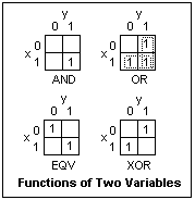 Karnaugh maps for two variables are shown at the left. There are 4 cells, and 14 ways to arrange 1's in them. Any map can be expressed as a sum (OR) of products (AND) of the two variables. This may not be the only way to express it, but it is one way. Indeed, the four cells are /x·/y, /x·y, x·/y and x·y, and these are just the four functions with only one 1. Of these, the one corresponding to x AND y is shown at the upper left. All can be written down at once from the definitions of the functions. The function EQV (≡) may be unfamiliar: it yields 1 if x and y are the same, 0 otherwise, the inversion of the XOR (≠) function. Think of each cell as part of a Venn diagram to write out an expression for the function. XOR, for example, is x·/y + /x&midddot;y, while EQV is x·y + /x·/y.
The OR function could be written as the sum of three terms, one for each 1, but it is better to write it as the OR of two terms corresponding to the areas of the "looped" 1's. One of these areas is just x, and the other y, so that the function is x + y, as is expected. This is the simplest example of such areas in a Karnaugh map. The larger such a rectangular array of 1's is, the simpler is its Boolean expression. The function represented by a 1 in each of the four cells, in which the whole universe is covered, is simply the constant 1. When all the cells are empty, the function is the constant 0. The K-maps of complemented functions are found by interchanging 1's and 0's. Show that the complement of x XOR y is the same as its dual.
K-maps are merely a cunning way to write the truth table for a Boolean function. In a truth table, the inputs are listed, usually in binary number order, and opposite each set of inputs is the value of the function, 1 or 0. A Boolean function is completely specified by its truth table, and the truth table contains a finite number of rows.
Digital Design
In digital design, the Boolean variables are high (H) and low (L) voltage levels on conductors that are interpreted as 1 and 0 (positive logic) or 0 and 1 (negative logic), and the two cases are the duals of each other. A Boolean function is the output of a circuit that depends on the levels of the input conductors. A circuit that outputs an H only when both inputs are H is conventionally called an AND gate (LS08), which it is for positive logic. For negative logic, it is an OR gate. Similarly, a circuit that outputs an L only when both inputs are L is called an OR gate (LS32), which it is for positive logic. For negative logic, it is an AND gate. The actual basic circuits have an inversion at the output, represented by a small circle called an inversion bubble, and are called NAND (LS00) and NOR (LS02) gates.
Only two levels are used in digital logic so that errors of interpretation can be reduced to insignificance, trading bandwidth for this essential feature. Computers must operate without digital errors. When a human makes an error, an exceedingly common event, it is only an inconvenience and a delay. An error in a computer system can bring everything crashing down, and is no trivial matter. Fast modems, which make use of multilevel logic, are made possible by automatic error detection and correction.
Making use of de Morgan's theorem, it is easy to show that either NAND gates alone, or NOR gates alone, can realize AND, OR and inversion, and so any logic function whatever. Work this out for yourself, and show that it is true. We can replace an AND gate by an OR gate with inversion bubbles at its three terminals, or an OR gate by an AND gate with inversion bubbles at its three terminals. This is simply de Morgan's theorem in action. Two inversion bubbles on the same conductor eat each other, but if they occur at the two ends, they are generally left to show that the logic level is inverted on this line. With these rules, you can modify digital circuits to find a better configuration.
For Boolean functions of one or two variables, there is little need for advanced methods, and solutions quickly suggest themselves. One simply has to be familiar with the available integrated circuit packages and their characteristics. Most actual problems are of this type, but they can hardly be considered problems.
For four variables, the K-map is specially convenient, since it can be drawn in a simple form, and the problems can be complex enough for the method to be valuable. The case of three variables is intermediate; K-maps are easily drawn and used, but the problems are not very difficult. K-maps can also be drawn for five or six variables, but are a bit like Mr Spock's multidimensional chess game and less than easy to visualize. In every case, however, the principles are the same. For more variables than four or possibly five, computer methods of simplification (minimization) are useful and rather powerful. However, the profitablility of such analyses is doubtful, and are applicable to problems that are no longer of much importance, since complex logic is no longer constructed from discrete gates.
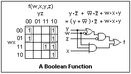 A K-map for a function of four Boolean variables is shown at the right. It is an arbitrary function, defined by putting 1's wherever a 1 ("true") output is desired. Note how the values of w, x, y and z are arranged, so that the areas on the Venn diagram that are contiguous are contiguous in the K-map. In going from one cell to a neighboring one, horizontally or vertically, the value of only one variable may change. Hence the order is 00, 01, 11, 10--not the order of increasing binary numbers. Also note that the diagram is continued from the right edge to the left, and from the bottom to the top, since the regions are contiguous.
This function has 7 1's that can be grouped into two rectangular groups of 4 and one rectangular group of 2, as shown by the dotted lines. This means the function can be expressed as the OR of two terms with two variables, and one with three, as shown. In this example, this is the only way the 1's can be grouped, but in some cases there may be alternatives. The largest groups give the smallest number of terms, but any of the many possibilities will give the correct function. In this case, we can factor out /z to give an alternative expression that may be simpler. Any (correct) algebraic manipulation will also give correct expressions that may be used to realize the function. One possibility, suggested by the factoring, is shown in terms of logic gates. Using Boolean algebra, the circuit can be made to use fewer types of gates, or different types of gates, or fewer inputs. There may be other factors as well, including propagation times, elimination of transient glitches, or economy in the integrated circuit packages used. It is these things that make digital design more than a trivial, straightforward exercise.
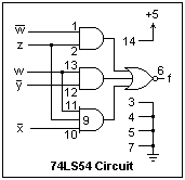
The K-map naturally expresses a Boolean function as the OR of several AND products. This is called the disjunctive normal form, and is a standard way to express the function. There are digital integrated circuits that perform the AND-OR-Invert function, and do it quickly. If you interchange 0's and 1's in the K-map and proceed directly, the solution will come out directly in AND-OR-Invert form. The 74LS55 has two 4-input AND gates, whose outputs are OR'ed and inverted. This circuit directly realizes any logic function of four variables whose K-map has 1's in any two different cells. The 74LS54 has AND gates with 3, 2, 2 and 3 inputs, and can realize functions where the 1's are suitably grouped. The function of the preceding paragraph can be realized with this chip. It is usual to assume that the variables and their complements are available. The AND-OR-Invert solutions have the shortest propagation times in general. Using the LS54 gives less than two delay times (20 ns), and involves only one IC package, while the solution in the figure above gives three delay times (45 ns) and uses parts of at least two IC's (LS32 and LS10). AND-OR-Invert gates were very useful when people built counters and shift registers from discrete gates, but designers no longer seem to know their advantages. There is no HC54 (just the HC51, the only survivor). AND-OR-Invert structures can still be seen in the internal circuits of IC's, however.
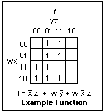 As a concrete example, consider the realization of the digital function discussed above in AND-OR form. The first step is to construct the K-map for the complementary function, which is shown in the figure at the left. The 1's are grouped into two groups of four, and one group of two, and the function written down in AND-OR form. The 74LS54 can realize this expression, as shown in the circuit below, with the pin numbers shown. Pin 8 is a no-connection. One of the three-input AND gates is a spare, and an input is tied low to remove it from the circuit. This circuit was tested for each of the 16 possible input states, and was found to realize the desired function (with a propagation delay of only 20 ns).
 The most useful skill in intermediate digital design is knowing how to use the available MSI (medium-scale integration) packages to realize logic solutions. Combinatorial logic, where the outputs are functions of the current inputs only, is easily realized with data selectors and similar circuits, and sequential logic, where the outputs depend on past inputs, by shift registers and counters. Static random-access memory can be used to realize arbitrary functions of large numbers of variables. The inputs are put in as the addresses, and the data are the values of the functions. A 1 bit x 64K memory (actually LSI, large-scale integration) can realize any logic function of 16 variables, should you need it. K-maps and such are of little use here, however.
There are also programmable logic devices, both field and mask programmable, of various structures, including AND-OR-Invert. The methods of digital design may be quite valuable here, even though we are not working with discrete gates. In effect, you choose the circuit that you want by blowing fuses where you do not desire connections.
Relay Logic
Mechanical switches and electromechanical relays have survived because of their desirable properties of (1), providing complete disconnection or low-resistance connection; (2), independence of voltage levels; and (3), ruggedness. Their greatest disadvantages are a limited mechanical life, usually determined by the contact conditions, and operating times in the millisecond range. Since their utility in control and logic circuits is still important, though almost completely neglected in modern texts, a discussion of their logic properties will be given here. There is no space here to discuss the physical properties of switches or relays, other than the briefest mention, and even the discussion of logic properties will be limited to a few examples. However, this should be enough to provide a good introduction to the use of switches and relays.
Mechanical switches are as old as electricity, and the relay was invented by C. A. Steinheil of Munich about 1838 (and later by others, more or less independently, since it is not an obscure concept). Boolean algebra was applied to switching circuits in 1939, though there was much earlier work that proceeded without its aid. It is useful for description and manipulation, but has little heuristic value, unfortunately. Relays were used in complex control circuits for railway signals beginning in the 1890's, and later were the logic elements in the first digital computers. Telephone circuit switching was a very important application of relays and automatic apparatus.
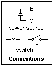 Some of the circuit diagram conventions that I shall use are shown at the right. The letters B ("Battery") and C ("Common") will be used instead of battery and ground symbols, both for conciseness and to avoid unnecessary specification of polarity. B may be positive or negative with respect to C, and this will have no effect in the unipolar circuits that I shall discuss. Curiously, railway signal engineers have assigned positive polarity to the short line in the battery symbol, instead of the currently more usual long line. A switch is labelled with a letter like "x" that represents a Boolean variable: switch open is x = 0, closed is x = 1. Instead of using the switch symbol, a break in a line representing a conductor containing the corresponding letter is used for simplicity. A capital letter, such as X, represents a complex circuit of switches. When X = 0, there is no conducting path, while X = 1 signifies a conducting path, equivalent to a closed switch. We are concerned only with connectivity, not with voltage or current levels.
Mechanical switches are classified by the number of poles, or independent elements, and the number of positions to which each pole may be connected. The most common forms of switches are denoted by the shorthand SPST, SPDT, DPST and DPDT, the meanings of which should be familiar. In moving from one position to the next, the old contact may be broken before the new one is made (non-shorting), or the new contact may be made before the old one is broken (shorting). This detail may have important effects. A good contact must wipe, not simply touch, and must be kept clear of corrosion. If the current rating of a switch is exceeded, either the life will be shortened or the switch may fail to break the circuit cleanly. DC is much more difficult to interrupt than AC. A switch with a rating for 125 VAC will have the same rating for 24 VDC, and the rating is inversely proportional to the voltage (roughly).
 Switches in series or parallel represent the Boolean operations of AND and OR, as shown in the diagram at the left. This means they have the same truth table, with 1 = connection. Any series-parallel combination of switches can be represented by a Boolean function, and all our algebraic resources can be used to find equivalent series-parallel combinations, perhaps some simpler than the one we are given. However, the world of switch networks is wider than this, and there are many circuits that cannot be represented directly by Boolean functions, only equivalent series-parallel circuits. This is one important limitation of Boolean algebra in switching circuits: it cannot lead to other than series-parallel equivalents.
 An example of a non-series-parallel circuit is shown at the right, the familiar "bridge" circuit. In addition to the paths ab and cd, there are also aec and deb, so its Boolean representation is X = ab + cd + aec + deb, which gives no hint as to its physical structure. Non-series-parallel circuits, which are generally more economical than equivalent series-parallel circuits, must be discovered by ingenuity, not Boolean algebra.
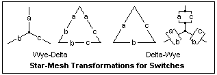 The wye-delta and delta-wye transformations (special cases of the star-mesh and mesh-star transformations) may be familiar to you from circuit theory. The equivalents for switching logic are shown at the left, and are fairly obvious to derive, remembering that two equivalent circuits must have the same truth tables. This transformation can reduce a non-series-parallel circuit to a series-parallel circuit (or vice-versa). Try it on the bridge circuit of the preceding paragraph, and reduce the result to the function X expressed there.
 Our example for switch logic is the classic and familiar problem of the light that is to be controlled from two different locations. Either location must be able to turn the light on or off, independently of the position of the switch at the other point. The K-map for this problem is shown at the right. For either value of y, the function can be made 0 or 1 by adjusting x, and vice-versa, so the corresponding logic function will do the job.
 The circuit shown at the left will do the job. The switches x and /x are combined in one unit, an SPDT switch, that ensures that the two outputs are complementary. Study the circuit for a minute to understand clearly why it works. Whichever wire happens to be connected with the lamp L at the y end, this wire can be energized by one or the other position of the switch x. This circuit is not just a result of Boolean algebra, but also could be found by ingenuity and reasoning.
 Let's now generalize the problem. Suppose you wished to control the light from a third position as well, as suggested by the diagram at the right. What can you put in place of the "?" ?. Do you need more wires? Write down the K-map for this problem the same as for the two-station case. The result will be a map with 1's and 0's in a kind of chessboard arrangment. No simplification by looping 1's can be made in such a case, but this K-map is a very characteristic one. For two variables (as above) it yields the EQV operation, or the XOR for the complement. It's useful to be able to indentify this particular K-map when it occurs.
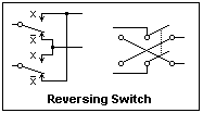 If you cannot see how to solve the problem at once by reasoning, design a circuit based on the K-map and consider it to see if it contains any hint. What the K-map gives is that a reversing switch at the position of the "?" solves the problem, with no additional wiring. This is the same solution that can be found by thinking. A reversing switch is shown at the left. A DPDT switch is required, wired as shown. The diagram at the right may be more familiar. Now, the solution for control from N positions should be obvious. One simply inserts a reversing switch at any desired control point.
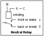 The representation of a neutral relay is shown at the right. It has a coil or winding on a magnetic core. A current through the winding produces a magnetic flux that attracts the armature holding the contact fingers, changing the connection from the back contacts to the front contacts (so named from the physical position on early relays). The contacts are returned to the unenergized position by gravity or a spring. The drawing shows the contacts as if falling by gravity, rising by attraction. All contacts associated with the same winding operate simultaneously. The control circuit is shown, from B to C through the winding, controlled by the Boolean function X that is some arrangement of switches. In this case, switches usually means other relay contacts, and only rarely an actual mechanical switch. When X = 1, then the relay picks up and x = 1, /x = 0 if the contacts are labelled as shown. The relay is an amplifying device, analogous to a vacuum tube or transistor, and can serve many of the same functions. It is, however, a strictly digital device with only two states. Its power gain can be very high, but here we are talking about control circuits, where the power is as small as possible. Relays controlling large amounts of power are called contactors.
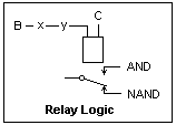 A relay can perform logic operations depending on the wiring of its control circuit and its contacts. In the figure at the left, xy in the control circuit determines the basic operation, while the output contact gives either AND or NAND. This is similar to diode logic, with the relay taking the place of the transistor as an amplifying element. It is easy to see how to realize an inverter or a buffer, both of which are often required.
A relay may be operated by AC as well as by DC, since the magnetic tractive force is independent of current direction. The great advantage of AC relays is their immunity to stray currents that arise whenever wires are out-of-doors. AC also gives the possibility of relays using motor action. A neutral relay is activated by the presence or absence of current only, while a polar relay depends on the polarity or phase of its operating current (AC polar relays often have two windings, one for a phase reference, while a DC polar relay may have a permanent magnet.) A relay may have both neutral and polar contacts. AC and DC polar relays are probably the apex of electromagnetic relay technology, but are difficult to find these days. They could be both sensitive and fast. When polar relays are used, positive and negative polarity are the two logic states; absence of current indicates a fault. Today's relays are mostly rugged, rather insensitive neutral relays with 4PDT contacts.
The relay winding has inductance, of course, so when the current through it is interrupted, an inductive kick results. This can cause sparking at the breaking contacts, which is not good for them. A rectifier diode connected across the winding with the cathode at the positive side will "catch" this inductive kick. The same trick is familiar from transistor switches, where it is essential. Here, it only helps extend contact life. Alternatively, a snubber can be connected across the breaking contact, consisting of a capacitor (say, 0.1 μF) and a small resistor (say, 100Ω) in series.
Sometimes, when attempting to simplify a circuit by using a section of it for more than one purpose, a sneak path may result that will give undesired operation of a relay, or other action. Often the current for the sneak path is in the reverse direction from the intended path. In this case, the sneak path can be eliminated by a blocking diode. Diodes were not available in the early days for catching inductive kicks and blocking sneak paths, but are now very useful adjuncts. One must also be wary of unwanted connections that result from the reuse of portions of a circuit.
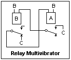 A relay multivibrator is shown at the left. Its frequency depends on the operating times of the relays. I found a frequency of 25 Hz with my relays, where I used catching diodes to eliminate sparking. The operating time of a relay may be lengthened by shading the magnetic circuit (applying a shorted conducting loop that opposes the rate of flux rise), by using a mechanical dashpot to slow the action, or even using a thermal element to delay the operation by seconds. These modifications may interfere with good contact action and cannot be used if any considerable power is controlled (unless the contact mechanism is changed to give some "snap" action).
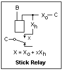 The relay analogue of the flip-flop is the stick relay, whose circuit is shown at the right. The control circuit of the relay includes a contact on the relay itself to give an alternative excitation path that can be closed when the relay operates. This hold circuit is controlled by the Boolean Function Xh. Therefore, the control circuit as a whole is characterized by the Boolean function X = Xo + xXh. An oscillator is created if /x is in the operating circuit, as in a doorbell buzzer.
Circuits involving stick relays are sequential, since the outputs may depend on past values of the inputs in addition to the current ones. This distinction between combinational and sequential circuits is important in digital design. The reader is referred to digital design texts for matters such as state diagrams and the general procedure for sequential design, all of which applies to relay logic as well. Here, I shall discuss only a simple sequential problem, that of determining the order of operation of two relays A and B. Different outputs should result if A closes before B or B closes before A.
In problems of this type, it is necessary to introduce secondary relays to distinguish different states of the system that may exist when the primary relays have the same values. These will be stick relays, corresponding to the flip-flops in usual digital design, and their values will define the states. In this case, an output light should light when A and B are both operated. A different light should light when A was first rather than when B was first, and this requires distinguishing the two cases. In this case, when A is activated while B is released, a third relay X is latched. X is not latched if B is activated first, so the two states are distinguished, and these two states have different outputs.
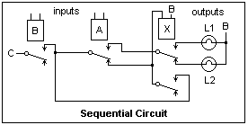 A circuit solving this problem is shown at the left. The input relays A and B are operated by some external source. They could be wiping contacts on a shaft if we wished to detect the direction of rotation. The direct path for operating relay X is cut through relays A and B, while the hold path returns to relay B. If B has already operated when X is energized by the operation of A, X will be latched. Otherwise, X will not be energized at all. The upper set of contacts of X controls the outputs. L1 = abx and L2 = ab/x are the output functions. The lights are lighted only when A and B are simultaneously energized. If it is desired to have a constant indication, the outputs could be applied as the set and reset signals of an SR flip-flop. You may be interested in solving this problem with IC digital logic, or in specifying and designing this circuit by the usual state machine design process.
Relays for testing any of the circuits mentioned above can be almost anything one can find at low cost. I have a number of 12 VDC relays with 4PDT contacts, the kind that come in a clear plastic cube 20 x 37 x 45 mm and fit into 14-pin sockets that make connections easy (Omron MY4). Everything is quite visible through the cover. Simply solder leads on the sockets and use them in a solderless breadboard. The resistance of the coils is 163Ω, so they draw about 74 mA. A 1 A supply will operate 13 such relays. Determine the pull-in and drop-out currents of your relays. The drop-out current is usually much lower than the pull-in current for these small relays.
References
Boolean algebra, in the form of switching algebra, is always treated in any text on digital design, along with binary numbers. Some classic texts that are not too bad are J. F. Wakerly, Digital Design Principles and Practice, 2nd ed. (Englewood Cliffs, NJ: Prentice-Hall, 1994) and C. H. Roth, Jr., Fundamentals of Logic Design, 4th ed. (St. Paul, MN: West Publishing Co., 1992). There are, of course, very many digital design texts, some of which have merit. The student will be disappointed at not being able to make a good practical circuit after studying these texts, but they are a first start.
H. G. Flegg, Boolean Algebra (London: MacDonald, 1971 and Transworld Publishers, 1972). A more mathematical introduction.
J. E. Whitesitt, Boolean Algebra and its Applications (New York: Dover, 1995 and Reading, MA: Addison-Wesley, 1965). Chapters 4 and 5 treat switches and relays.
Composed by J. B. Calvert
Created 14 July 2002
18 July 2002